PRODUCTS

Phone:0773-5850657
Fax:0773-5814532
Service:Miss.Yu
Mobile:Mr. Qin 18977333475
E-mail:5803731@163.com
Address:High-tech Zone Guilin, Guangxi, China Yi Feng South Road on the 16th
DACTS101S
DACTS-101S(V2.0) DIESEL GENERATORS CONTROL MODULE
1. DESCRIPTION
DACTS-101S is a diesel generator manual/automatic control module, it is used to start and stop the diesel generator via a key switch and three pushbuttons or an outer ‘grid fault’ switch, shutting down automatically the diesel when a diesel fault occurs and indicating the fault by the LED on the front panel.
The module has a LCD for displaying the diesel frequency, diesel speed and total run hours by turns.
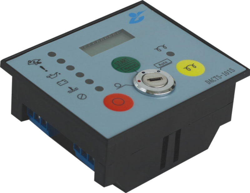
Operation of the module is via a key switch and three pushbuttons on the front panel. The key switch has 3 positions, they are Off(O), Manual and Auto.
Off mode O
If the key is turned to the ‘O’ position, the module is powered off at once.
Manual mode Manual
• Turn the key switch to ‘Manual’ position.
• Press the start button for long to start the diesel, then the module will exit from start status once the diesel comes true the success conditions for start.
• To stop the diesel the ‘O’ button needs to be pressed.
Auto mode Auto
• The key switch is turned to ‘Auto’ position.
• When the grid fault switch is closed, the diesel will be started automatically.
• The diesel will be stopped automatically if the grid fault switch turns open.
Only when the switch key is in ‘Manual’ position, the three pushbuttons are available.
[Stop/O]: pressing this pushbutton is to stop the diesel and reset the diesel fault if a failure occurs.
[Start]: press this pushbutton for long to start the diesel.
![]() [ ]: If the output 1 is set
to 0 or 1(0 indicates pre-fuel; 1 indicates pre-heat), pressed this button and maintained, the output 1 will
be energized until this button is released.
[ ]: If the output 1 is set
to 0 or 1(0 indicates pre-fuel; 1 indicates pre-heat), pressed this button and maintained, the output 1 will
be energized until this button is released.
The module provides six alarm channels, they are low oil pressure, high coolant temperature, emergency stop, over speed, charge failed, fail to start. Each alarm channel has it’s own LED indicator and once activated no further alarm conditions will be accepted. The alarm outputs and relevant LED, except for charge failed, will remain active until the diesel is reset via pressing the stop button.
After the warm up delay times out, if the grid has a failure and the output 2 is set to 0(0 indicates generator powered) and the frequency is normal (namely the frequency is over 45Hz at rated 50Hz system or over 54Hz at rated 60Hz system), then the generator powered output will remain energized, if the grid turns normal, this output will be de-energized.
The over speed trip is 1650prm at rated 50Hz system, or 1980rpm at rated 60Hz system. When the diesel speed exceeds the speed trip, an alarm for over speed will occur.
Note: the success condition for start is the diesel speed is over 300rpm, or oil pressure turns from low to normal.
2. OPERATION
Input password
![]() In Manual mode,
pressing the stop button for ten seconds, if the LCD shows 1P, input the first
password number via pressing the start button (equal to increase function) or button(decrease function), then press stop button to confirm, here the stop button acts as
enter function. The default password is 3333.
In Manual mode,
pressing the stop button for ten seconds, if the LCD shows 1P, input the first
password number via pressing the start button (equal to increase function) or button(decrease function), then press stop button to confirm, here the stop button acts as
enter function. The default password is 3333.
Within 10 seconds none of operations is made to any of the pushbuttons, the display will automatically exit from the setting status.
Parameters setting
You can access the parameters menu after finishing the password input. The module has a parameters list, all the parameter is described by the numbers, the user is allowed to change the settings of all the parameters.
On the default display, if you want to change the setting, then press the stop button.
Under the parameter setting mode, the start button function is to increase or progress, the pre-heat button is to decrease or back up and the stop button is to enter.
For example, the following operation is for changing the start times from 3 to 5.
• Pressing the stop button for 10 seconds,
• Press the start button for two times to increase the value to 5 on the right.
• Again press the stop button to confirm, then the LCD automatically displays the next parameter.
The parameters list is as follows.
Number |
Parameter |
Default value |
Set range |
|
System parameters |
|||
|
00 |
Start times |
3 |
1~8 times |
|
01 |
Fuel mode |
0 |
0/1 |
|
02 |
Gear teeth |
128 |
0~255 |
|
03 |
Frequency setting |
50Hz |
50 / 60Hz |
|
04 |
Output 1 |
0 |
0/1/2/3/4 |
|
05 |
Output 2 |
0 |
0/1 |
|
Time delays (the unit is second) |
|||
|
06 |
Start |
6.0 |
1~10s |
|
07 |
Crank rest |
15.0 |
5~60s |
|
08 |
Start bypass |
10.0 |
0~60s |
|
09 |
Remote start |
5.0 |
0~6000s |
|
10 |
Generator-Grid transfer |
5.0 |
0~180s |
|
11 |
Stop fuel |
10.0 |
1~15s |
|
12 |
Pre-fuel |
5.0 |
0~30s |
|
13 |
Cool stop |
5.0 |
0~120s |
|
14 |
Speed up |
15.0 |
0~180s |
|
15 |
Warm up |
5.0 |
0~180s |
Parameter description
Fuel mode:
0-run output. The fuel output is energized when the diesel is to start, and will remain energized until the unit is signaled to stop or shuts down on fault.
1-stop output. When the diesel is needed to stop, the fuel output is energized and maintains for the period of a time delay stop fuel.
Gear teeth:
0 - Speed signal comes from diesel frequency.
>0 - Speed signal comes from magnetic pick-up.
Output 1:
0-pre-fuel; 1-pre-heat; 2-idle speed
Output 2:
0-generator powered; 1-idle speed
Time delay remote start: this delay is between the grid fault switch turns closed and the startup of the generator in ‘Auto’ mode.
Time delay Generator-Grid transfer: this delay is between the grid fault switch turns open, and the generator powered output is de-energize in ‘Auto’ mode.
Time delay stop fuel: this delay is only used if the module is configured with stop output. If so, when the diesel is stopped, the fuel output is energized, the stop fuel delay begins to time, the fuel output remains energized until this delay ends.
Time delay pre-fuel: this delay is only used when the module is in Auto mode. After a pre-heat delay, the diesel is started.
Time delay crank: the delay begins to time when the diesel is started, during the delay, the module detects the start success condition, if the condition is content, the module is signal the diesel is started successfully, and the start output is de-energized.
Time delay crank rest: the delay is used between crank attempts assuming the start times is set to more than one. When the time delay crank ends, if the diesel is not started successfully, the crank rest delay is initialized, after the delay times out, the crank delay begins to time, at the same time, the start times increase one.
Time delay start bypass: the bypass delay begins
after the diesel is started, during the delay, the module don’t detect the faults as low oil pressure, high coolant temperature and so on,
Time delay cool stop: following the Generator-Grid transfer delay, the cool stop delay begins to time, synchronously the generator powered output is de-energized, the diesel is allowed to run without load, following this delay, the diesel is stopped.
Time delay speed up: the speed up delay is initialized after the diesel is started successfully, when this delay times out, if the user-defined output 1 or output 2 is set to ‘1’, the idle speed has an output, the diesel will run in rated speed instead of idle speed.
Time delay warm up: following the speed up delay, the warm up delay is initialized, when this delay times out, if the grid has a failure, and the diesel frequency and speed are within normal limits, and the user-defined output 2 is set to ‘0’, then the generator powered has an output.
3. SPECIFICATION
• DC Supply: 8 to 32V DC.
•AlternatorInputRange: 0 to 250 V AC
• Alternator Input Frequency: 0 to 99 Hz
• Transistors Output: 1A DC
• Operating Temperature: -30 to +60°C
• Overall Dimensions: 87x72x38mm(Excluding Key)
• Cut-out Dimensions: 80 X 65 mm
• Installation Method: Front panel mounting via suitable cut-out. Retaining clips supplied. Cable connections via locking plug and socket type connectors.
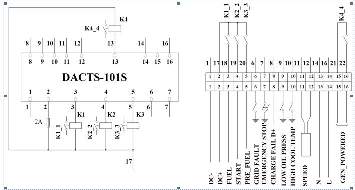
4. WIRING DIAGRAM